Electrical Series Circuit Worksheet
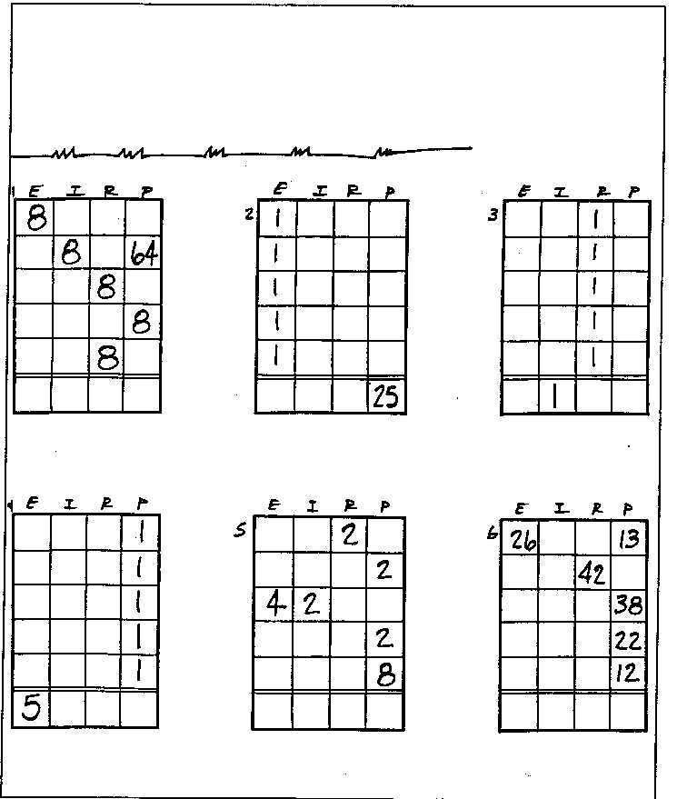
Are you a student or a teacher looking for a comprehensive worksheet on electrical series circuits? Look no further! This worksheet is designed to help you deepen your understanding of the basic concepts and principles of series circuits in a practical and engaging way.
Table of Images 👆
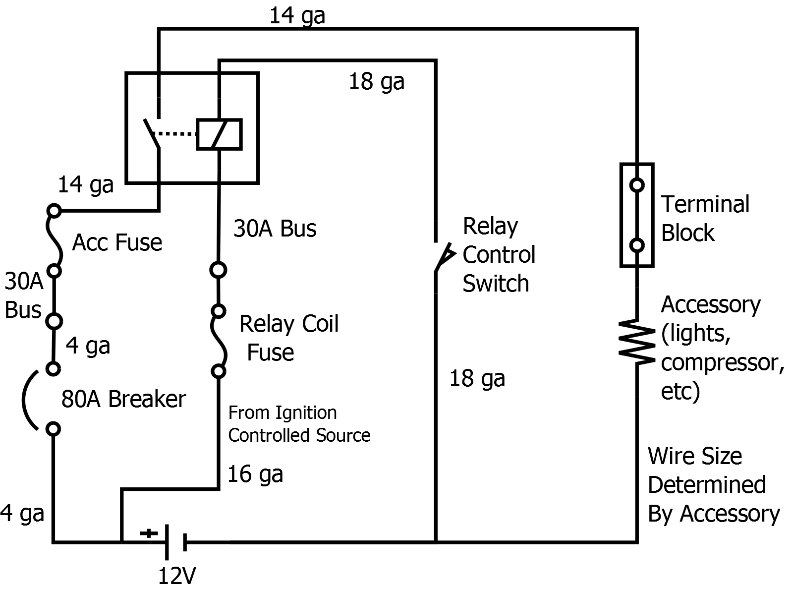
- Simple Electrical Circuit Diagram
- Series and Parallel Circuits Examples
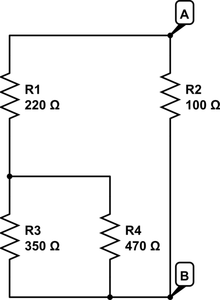
- Series Parallel Circuit Worksheet
- Hamilton Paths and Circuits Worksheets
- Parallel Circuit Problem Worksheet
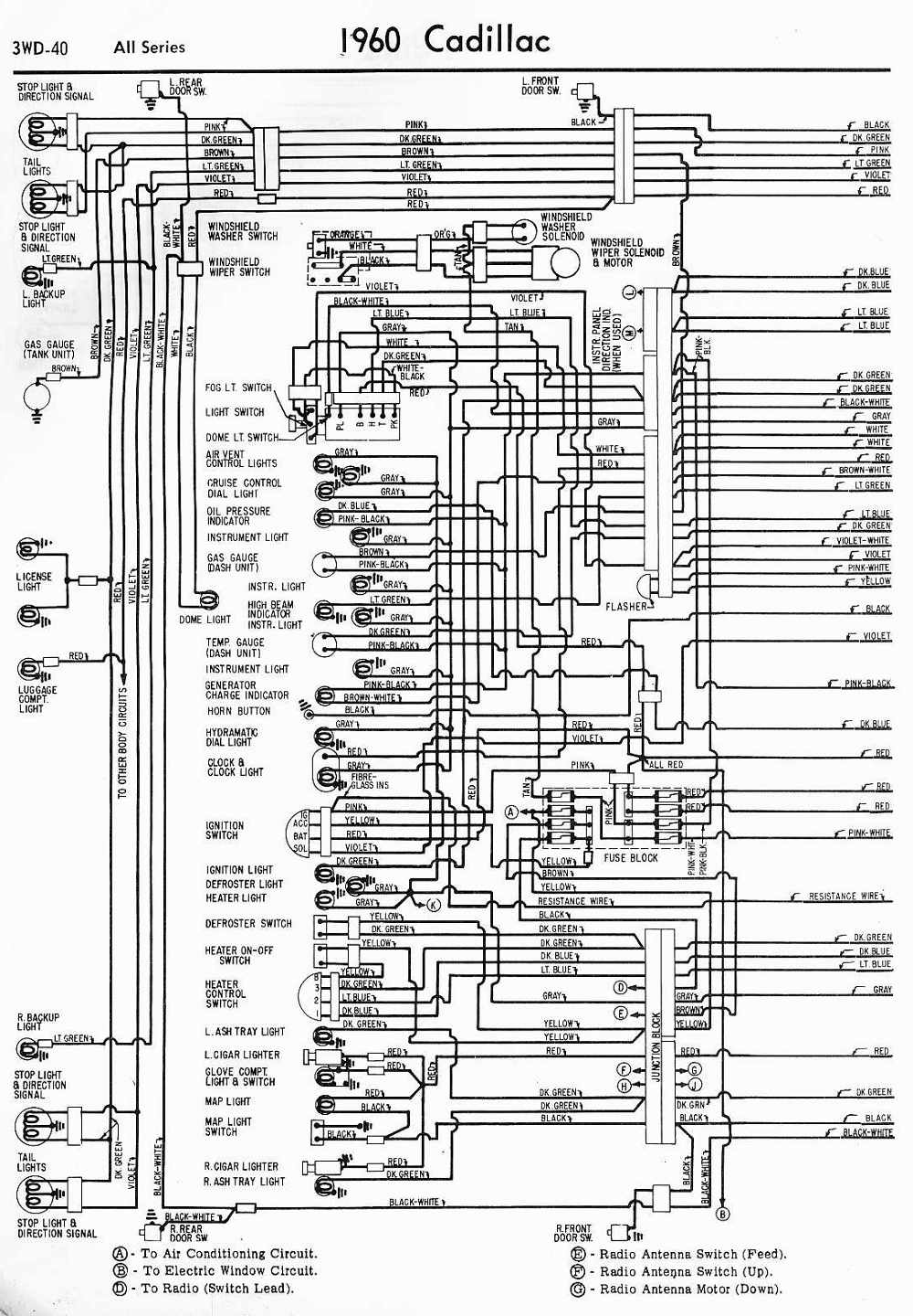
- 1960 Cadillac Wiring-Diagram
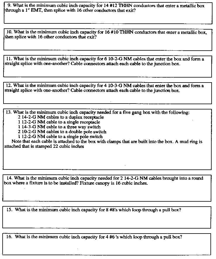
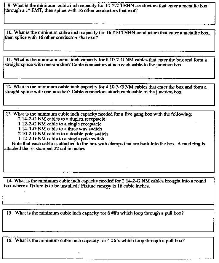
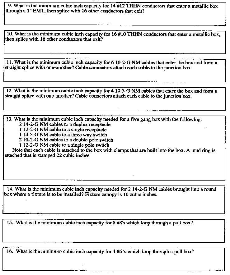
- Electrical Box Fill Calculation
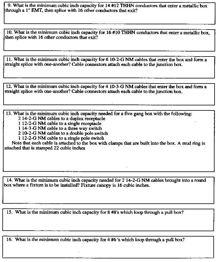
- Electrical Box Fill Calculation
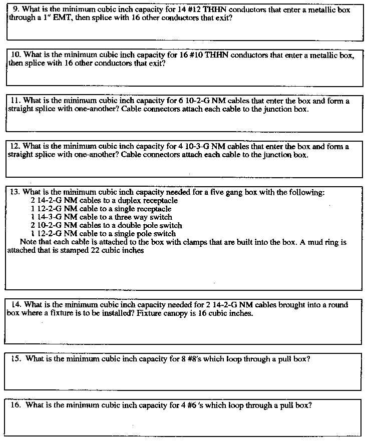
- Electrical Box Fill Calculation
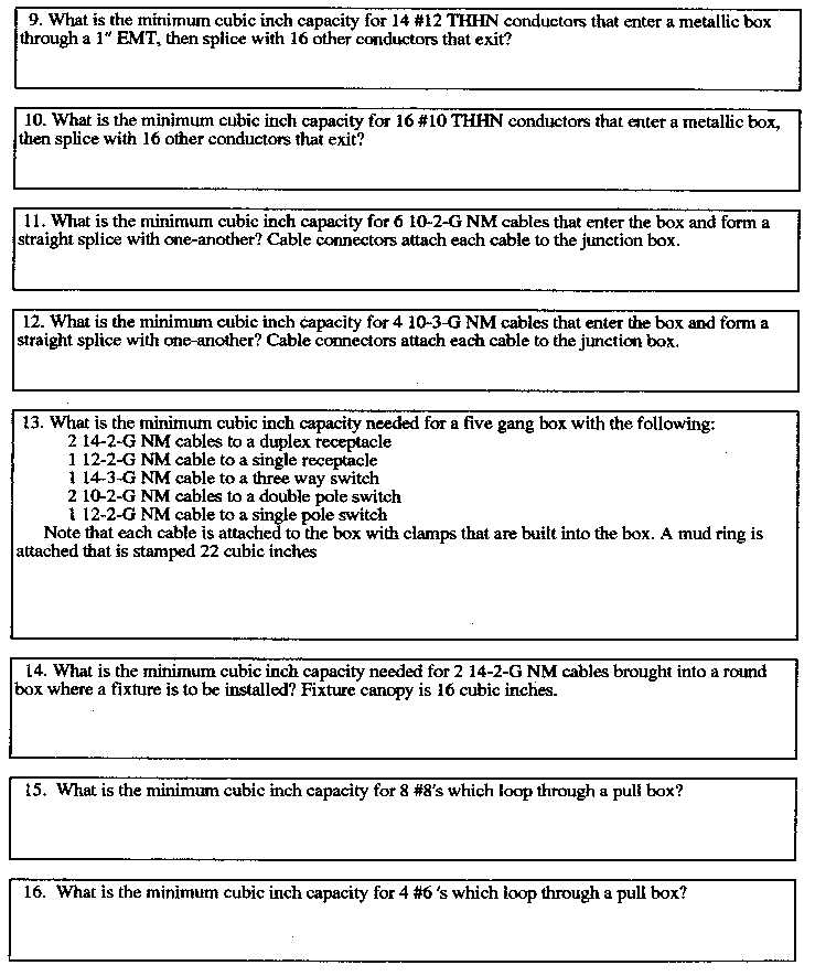
- Electrical Box Fill Calculation
- Electrical Box Fill Calculation
- Electrical Box Fill Calculation
More Other Worksheets
Kindergarten Worksheet My RoomSpanish Verb Worksheets
Healthy Eating Plate Printable Worksheet
Cooking Vocabulary Worksheet
My Shadow Worksheet
Large Printable Blank Pyramid Worksheet
Relationship Circles Worksheet
DNA Code Worksheet
Meiosis Worksheet Answer Key
Art Handouts and Worksheets
What is an electrical series circuit?
An electrical series circuit is a type of circuit where the components are connected in a single pathway so that the current flows through each component in a sequential manner. In a series circuit, the same current flows through all components, and the total resistance is the sum of the individual resistances. If one component fails or is removed, the circuit is open and current cannot flow.
How is the current distributed in a series circuit?
In a series circuit, the current is the same at all points throughout the circuit. This means that the same amount of electrical current flows through each component in the circuit, as there is only one path for the current to travel. The current is not divided or shared among the components in a series circuit, but instead remains constant throughout.
What happens to the resistance in a series circuit when additional components are added?
When additional components are added to a series circuit, the total resistance in the circuit increases. This is because resistance in a series circuit adds up, just like adding numbers in a row. The overall resistance in the circuit is the sum of the individual resistances of all components connected in series.
How does the total resistance in a series circuit compare to the individual resistances of the components?
In a series circuit, the total resistance is equal to the sum of the individual resistances of the components. This means that as more resistors are added in series, the total resistance of the circuit increases proportionally to the sum of all the individual resistances.
What is the formula for calculating the total resistance in a series circuit?
The formula for calculating the total resistance in a series circuit is to simply add up all the individual resistances in the circuit. Mathematically, it is expressed as R_total = R1 + R2 + R3 + ... + Rn, where R_total is the total resistance and R1, R2, R3, etc., are the individual resistances in the circuit.
How does the voltage divide in a series circuit?
In a series circuit, the voltage divides proportionally across each component based on its resistance. The voltage across each component is determined by its resistance relative to the total resistance in the circuit. The component with higher resistance will have a higher voltage drop across it, while the component with lower resistance will have a lower voltage drop. The total voltage of the circuit is equal to the sum of the voltage drops across each component.
What happens to the total voltage in a series circuit when additional components are added?
In a series circuit, the total voltage remains the same when additional components are added. This is because the voltage in a series circuit is divided among the connected components in proportion to their resistance, but the total sum of voltage across all components remains constant. Therefore, as components are added in series, the total voltage across the circuit does not change.
How does the total voltage in a series circuit compare to the individual voltages across the components?
In a series circuit, the total voltage is equal to the sum of the individual voltages across all the components. This means that the voltage across each component adds up to the total voltage applied to the circuit. So, the total voltage in a series circuit is distributed among the individual components.
How does the current in a series circuit change with different components?
In a series circuit, the current remains constant throughout the circuit regardless of the components. This means that the current passing through each component in a series circuit remains the same and is equal to the total current supplied by the voltage source. Changing the components in a series circuit will not affect the current flowing through the circuit as long as the voltage source remains the same.
How does a break or open circuit affect the flow of electricity in a series circuit?
In a series circuit, a break or open circuit will interrupt the flow of electricity and prevent it from passing through the entire circuit. This interruption creates a gap in the path of the current, causing no electricity to flow beyond the break point. As a result, any components or devices after the break in the circuit will not receive the electricity needed to operate, effectively shutting them off.
Have something to share?
Who is Worksheeto?
At Worksheeto, we are committed to delivering an extensive and varied portfolio of superior quality worksheets, designed to address the educational demands of students, educators, and parents.





Comments