Electrical Schematics Worksheet
Electrical schematics worksheets serve as essential tools for both novice and experienced engineers seeking to streamline their design and troubleshooting process. These worksheets are specially designed to provide a clear visual representation of an electrical circuit, helping engineers understand the entity and subject they are working with in a concise and organized manner.
Table of Images 👆
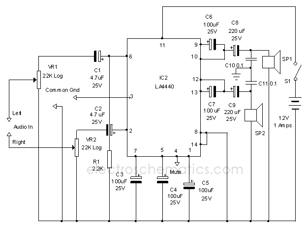
- Audio Amplifier Circuit Diagram
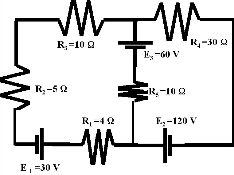
- Electrical Circuit Examples
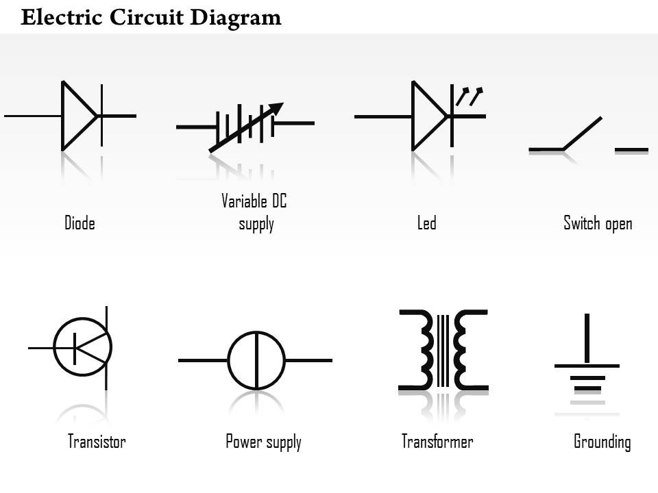
- Electrical Transformer Diagram
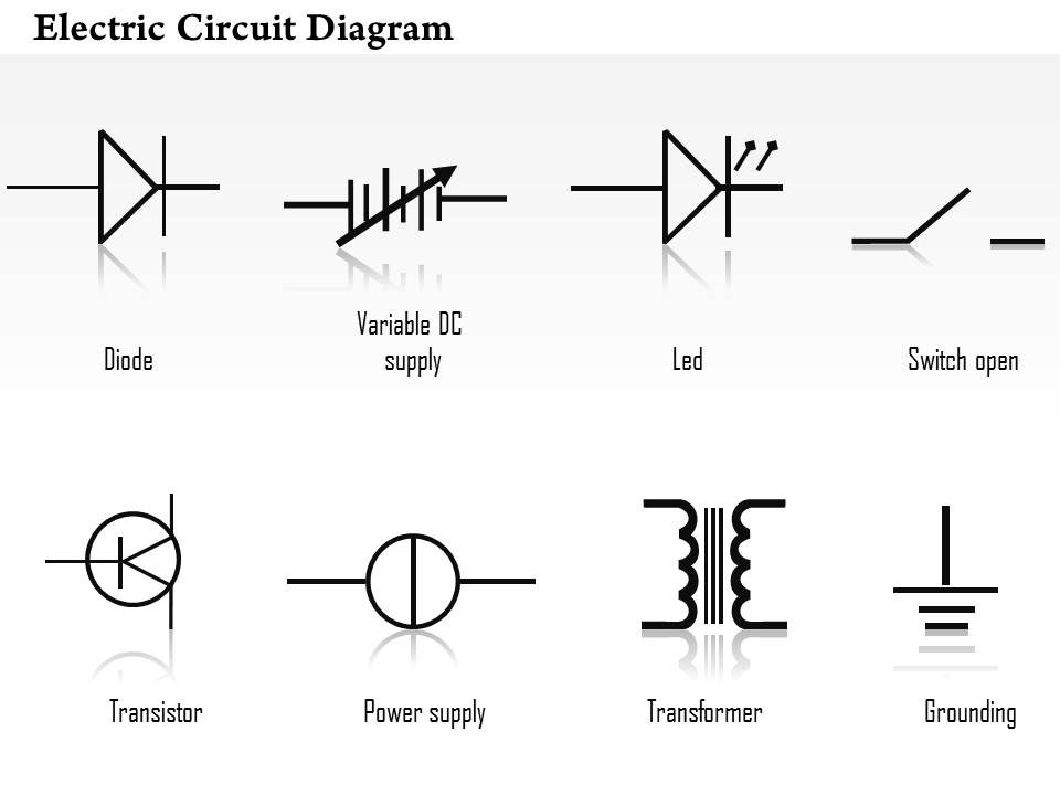
- Electrical Transformer Diagram
- Electrical Transformer Diagram
- Electrical Transformer Diagram
- Electrical Transformer Diagram
- Electrical Transformer Diagram
- Electrical Transformer Diagram
- Electrical Transformer Diagram
- Electrical Transformer Diagram
- Electrical Transformer Diagram
- Electrical Transformer Diagram
- Electrical Transformer Diagram
- Electrical Transformer Diagram
- Electrical Transformer Diagram
- Electrical Transformer Diagram
- Electrical Transformer Diagram
More Other Worksheets
Kindergarten Worksheet My RoomSpanish Verb Worksheets
Cooking Vocabulary Worksheet
My Shadow Worksheet
Large Printable Blank Pyramid Worksheet
Relationship Circles Worksheet
DNA Code Worksheet
Meiosis Worksheet Answer Key
Art Handouts and Worksheets
7 Elements of Art Worksheets
What is an electrical schematic?
An electrical schematic is a diagram that represents the electrical connections and functions of a system or circuit using standard symbols and conventions. It provides a visual representation of the components, connections, and paths of electrical currents within the system, allowing for easier understanding and troubleshooting of the circuit design.
What is the purpose of an electrical schematic?
An electrical schematic is used to represent the connections and functions of electrical components in a clear and standardized way. It serves as a detailed blueprint that allows engineers, technicians, and electricians to understand, troubleshoot, and repair electrical systems by providing a visual representation of how components are interconnected and how they work together to achieve a specific function.
What are the common symbols used in electrical schematics?
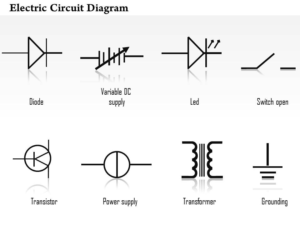
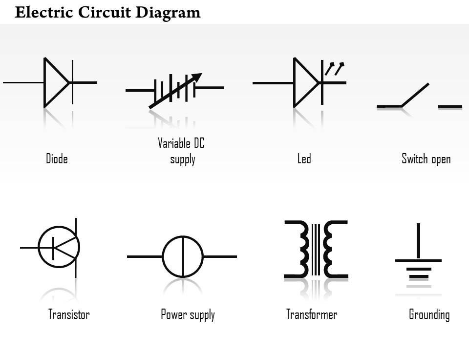
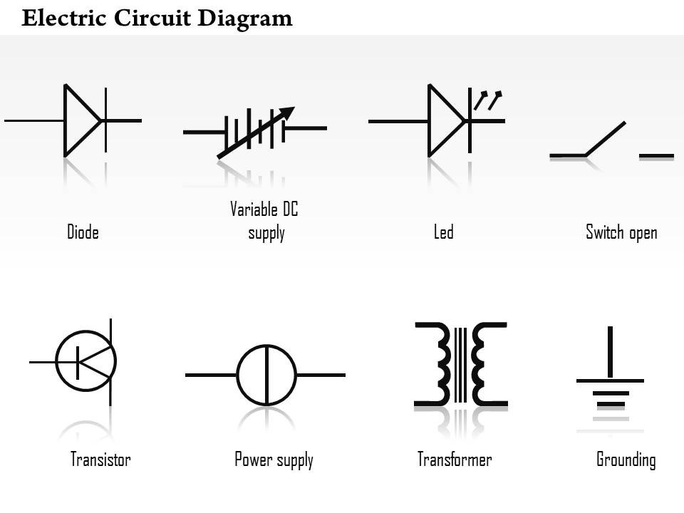
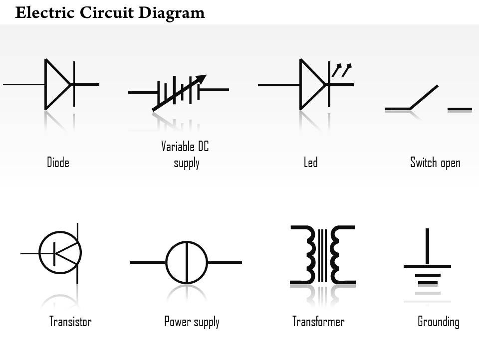
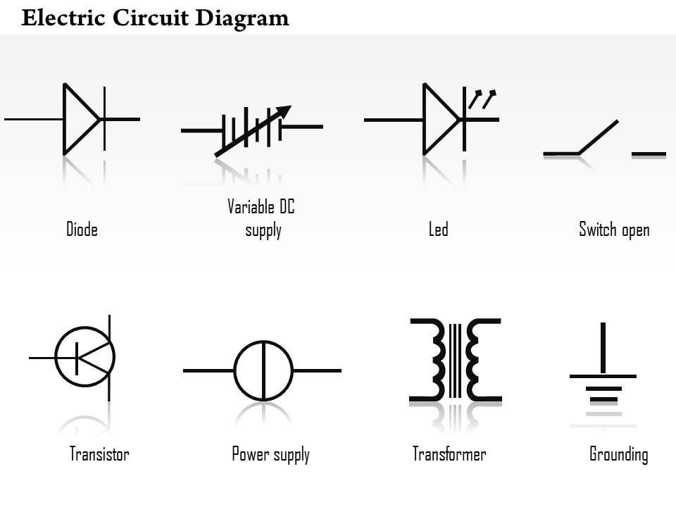
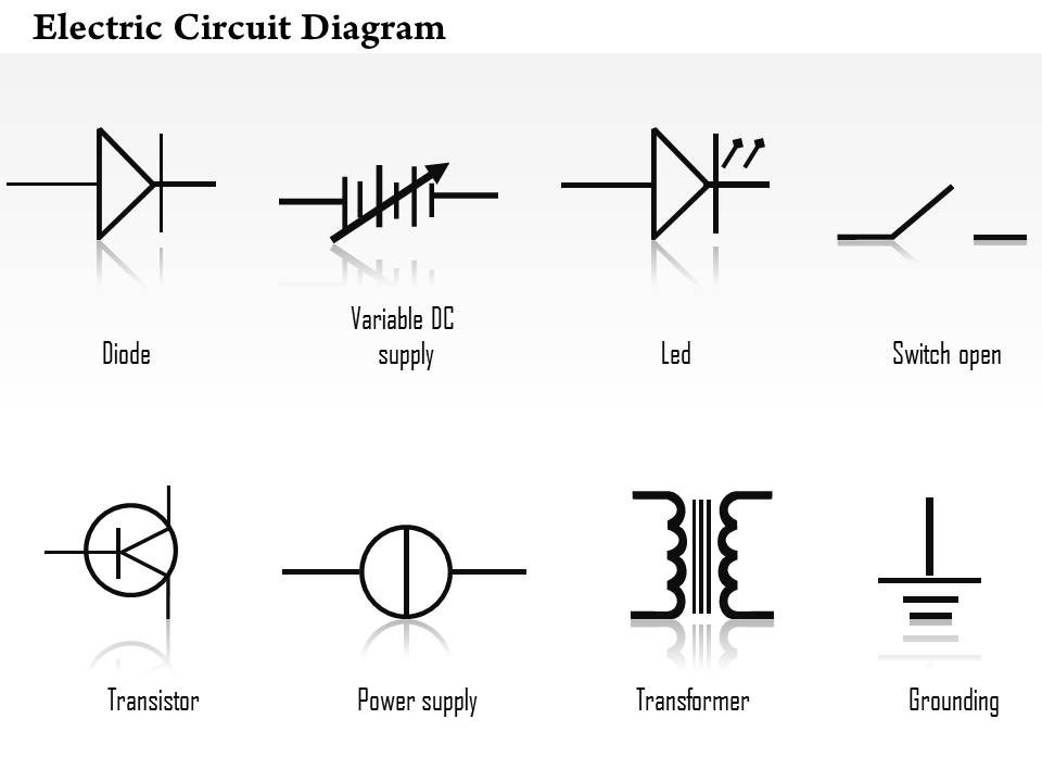
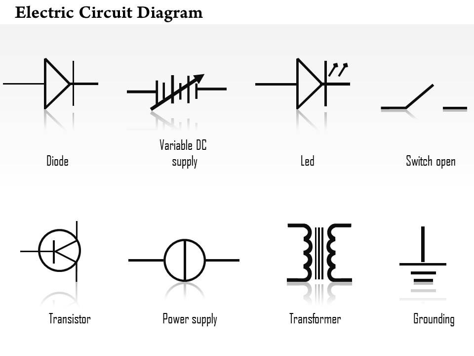
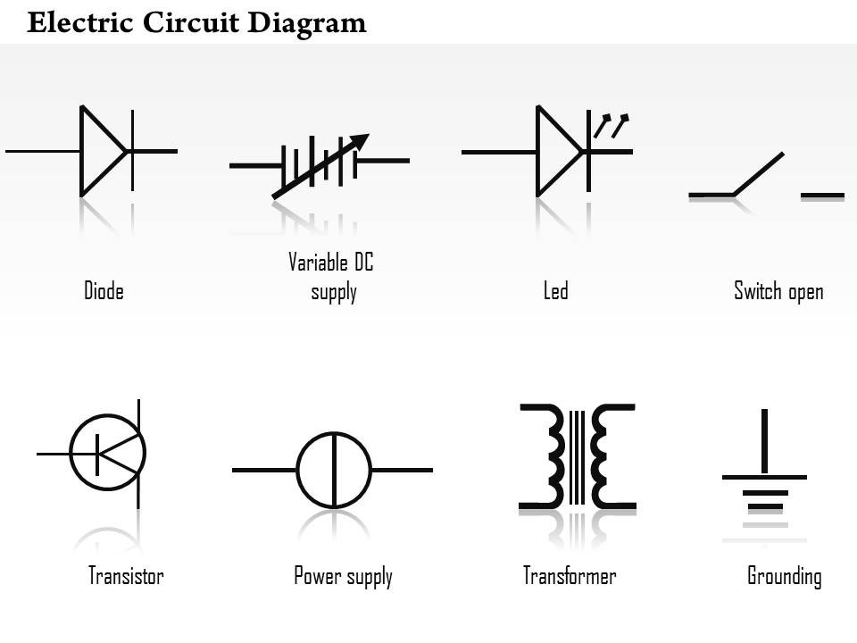
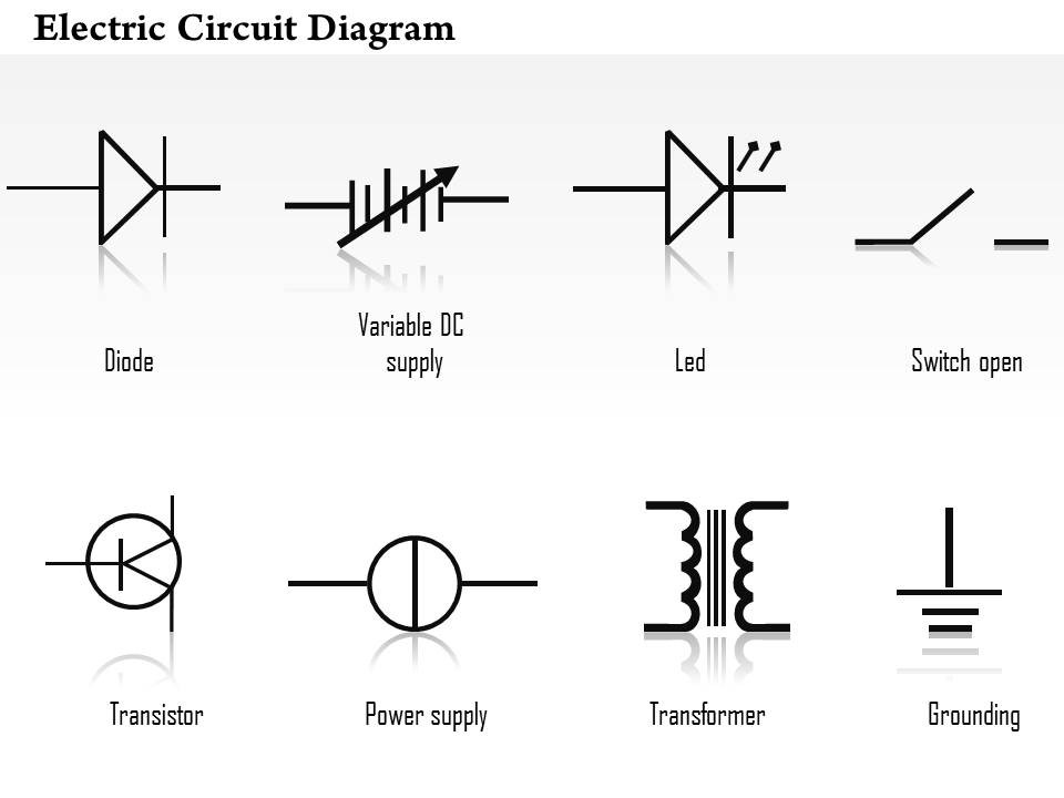
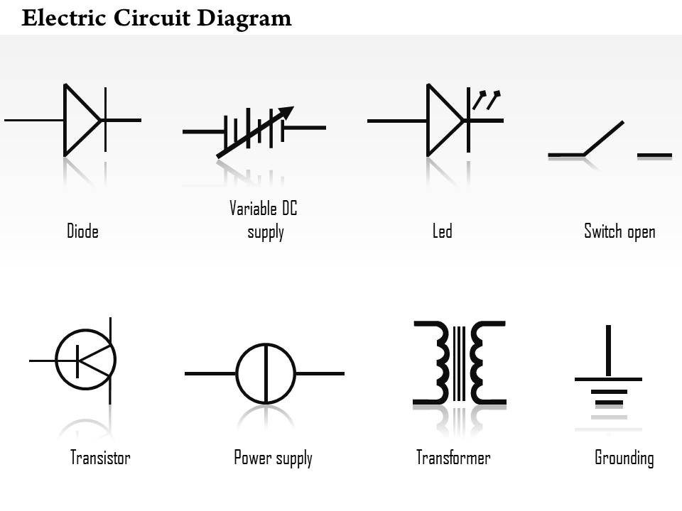
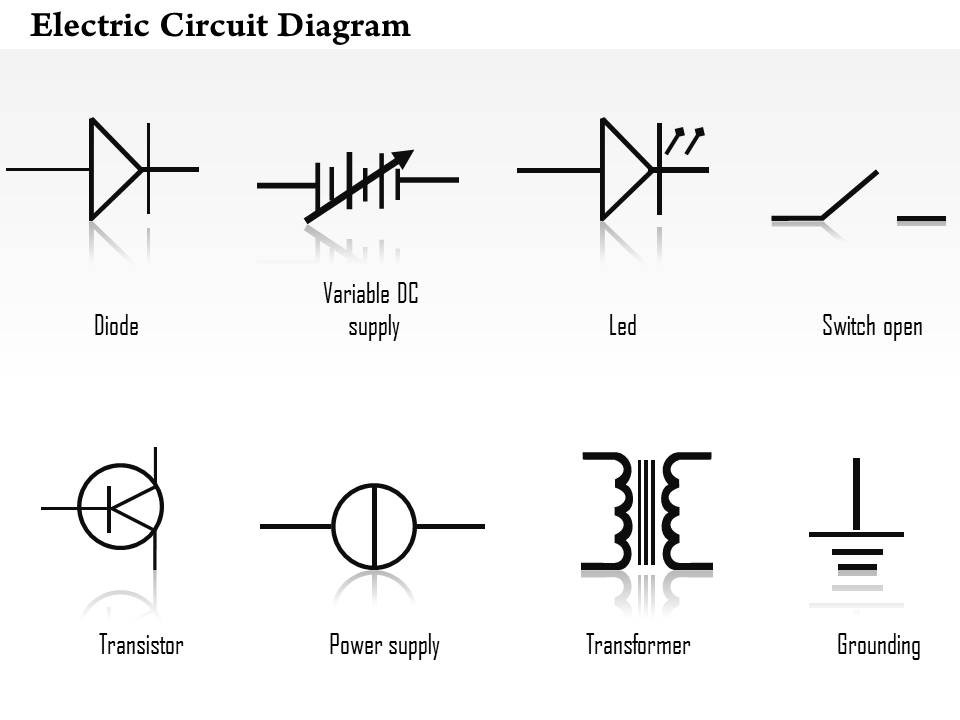
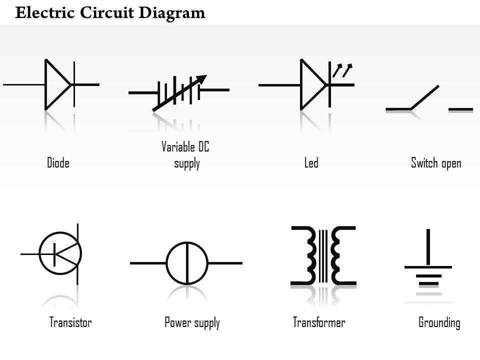
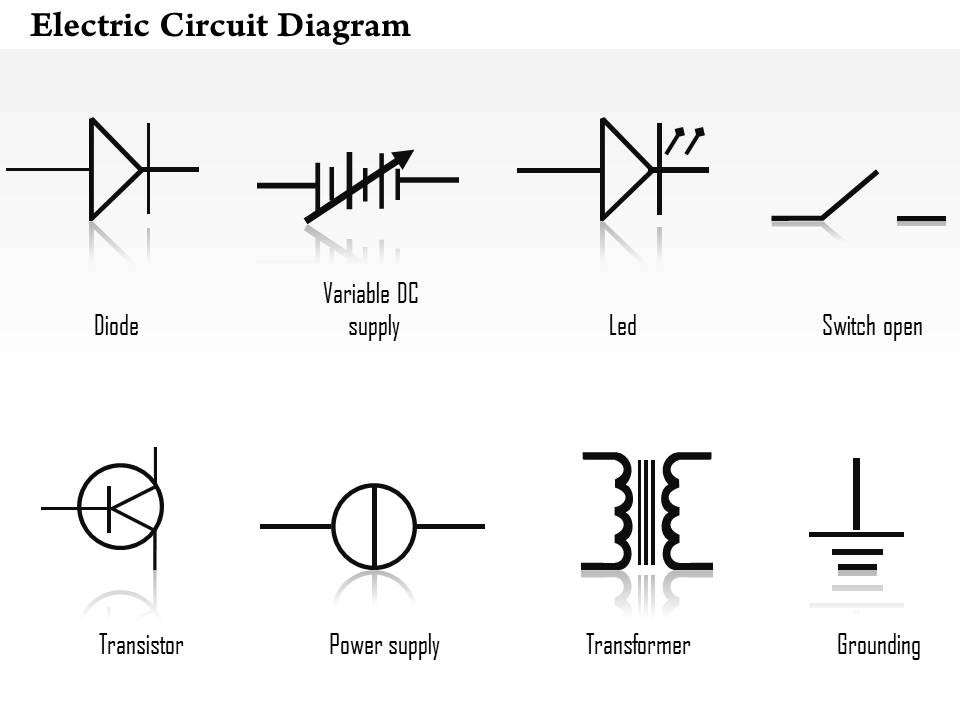
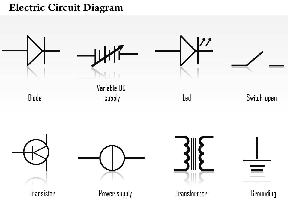
Common symbols used in electrical schematics include lines to represent wires, circles for junctions or nodes, triangles for grounds, rectangles for components, arrows to indicate flow of current, and various shapes to represent different types of switches, resistors, capacitors, inductors, transformers, and other electronic components.
How are electrical components represented in a schematic?
Electrical components are typically represented in a schematic diagram using standardized symbols that convey their function and structure, such as resistors, capacitors, transistors, and connectors. These symbols allow engineers and technicians to easily interpret and understand the electrical circuit design, making it simpler to identify and troubleshoot issues within the system.
How are wires and connections shown in an electrical schematic?
Wires and connections in an electrical schematic are typically represented by lines connecting components, switches, and other elements. The lines may have different styles and symbols to indicate the type of connection, such as a straight line for a normal connection or a dashed line for a hidden connection. Junction points where wires intersect are usually denoted by a dot or a small cross to show that they are electrically connected. This method of representing wires in electrical schematics helps to visually illustrate the flow of electric current and the connections between different components in a circuit.
What is the importance of labeling and numbering in a schematic?
Labeling and numbering in a schematic are crucial because they provide clear organization and aid in easy referencing of components and connections. This helps in the troubleshooting process, allows for easier communication among team members, ensures accuracy in assembly processes, and facilitates maintenance and repair activities. Proper labeling and numbering help to streamline operations, reduce errors, and enhance overall efficiency in working with schematics.
How are different circuits and sections distinguished in a schematic?
Different circuits and sections are typically distinguished in a schematic diagram through the use of labels, symbols, and connecting lines. Each circuit or section is usually enclosed within a boundary or outlined with a thicker line to separate it from other parts of the schematic. Additionally, labels and unique identifiers are often used to differentiate each circuit or section, making it easier to identify and understand the overall layout and connections within the schematic. Symbols representing various components are also used to visually represent different parts of the circuit, further aiding in distinguishing one section from another.
What are some key guidelines for creating clear and accurate electrical schematics?
Some key guidelines for creating clear and accurate electrical schematics include using standardized symbols and labels, organizing the schematic in a logical and easily understandable layout, providing a clear and concise title and key, using consistent colors and line styles for different components, ensuring proper sizing and spacing of elements to avoid clutter, and verifying the accuracy of the schematic through thorough reviews and testing. Additionally, it is important to document any assumptions or notes that may impact the interpretation of the schematic and to follow industry best practices and standards to ensure consistency and compatibility with other electrical systems.
How can electrical schematics help in troubleshooting and maintenance?
Electrical schematics are essential in troubleshooting and maintenance as they provide a detailed visual representation of an electrical system's components, connections, and functions. By referencing a schematic, technicians can quickly identify the flow of electricity, locate problematic components, and trace wiring to pinpoint faults or potential areas of concern. This helps streamline the troubleshooting process, saving time and reducing the risk of making errors. Furthermore, having accurate schematics on hand during maintenance tasks enables technicians to adhere to proper procedures, ensure components are installed correctly, and avoid causing damage to the system.
What are some software tools commonly used for creating and editing electrical schematics?
Some software tools commonly used for creating and editing electrical schematics include AutoCAD Electrical, EAGLE, KiCad, and Altium Designer. These tools provide features like symbol libraries, wire connection tools, and design rule checking to help engineers efficiently design and document electrical circuits.
Have something to share?
Who is Worksheeto?
At Worksheeto, we are committed to delivering an extensive and varied portfolio of superior quality worksheets, designed to address the educational demands of students, educators, and parents.





Comments